Filter: More Comfortable
Implement a program that applies filters to images.
$ ./filter -g image.bmp grayscale.bmp
Background
Bitmaps
Perhaps the simplest way to represent an image is with a grid of pixels (i.e., dots), each of which can be of a different color. For black-and-white images, we thus need 1 bit per pixel, as 0 could represent black and 1 could represent white, as in the below.
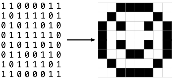
In this sense, an image is just a bitmap (i.e., a map of bits). For more colorful images, you simply need more bits per pixel. A file format (like BMP, JPEG, or PNG) that supports “24-bit color” uses 24 bits per pixel. (BMP actually supports 1-, 4-, 8-, 16-, 24-, and 32-bit color.)
A 24-bit BMP uses 8 bits to signify the amount of red in a pixel’s color, 8 bits to signify the amount of green in a pixel’s color, and 8 bits to signify the amount of blue in a pixel’s color. If you’ve ever heard of RGB color, well, there you have it: red, green, blue.
If the R, G, and B values of some pixel in a BMP are, say, 0xff, 0x00, and 0x00 in hexadecimal, that pixel is purely red, as 0xff (otherwise known as 255 in decimal) implies “a lot of red,” while 0x00 and 0x00 imply “no green” and “no blue,” respectively.
A Bit(map) More Technical
Recall that a file is just a sequence of bits, arranged in some fashion. A 24-bit BMP file, then, is essentially just a sequence of bits, (almost) every 24 of which happen to represent some pixel’s color. But a BMP file also contains some “metadata,” information like an image’s height and width. That metadata is stored at the beginning of the file in the form of two data structures generally referred to as “headers,” not to be confused with C’s header files. (Incidentally, these headers have evolved over time. This problem uses the latest version of Microsoft’s BMP format, 4.0, which debuted with Windows 95.)
The first of these headers, called BITMAPFILEHEADER, is 14 bytes long. (Recall that 1 byte equals 8 bits.) The second of these headers, called BITMAPINFOHEADER, is 40 bytes long. Immediately following these headers is the actual bitmap: an array of bytes, triples of which represent a pixel’s color. However, BMP stores these triples backwards (i.e., as BGR), with 8 bits for blue, followed by 8 bits for green, followed by 8 bits for red. (Some BMPs also store the entire bitmap backwards, with an image’s top row at the end of the BMP file. But this problem set’s BMPs are stored with each bitmap’s top row first and bottom row last.) In other words, were we to convert the 1-bit smiley above to a 24-bit smiley, substituting red for black, a 24-bit BMP would store this bitmap as follows, where 0000ff signifies red and ffffff signifies white; we’ve highlighted in red all instances of 0000ff.
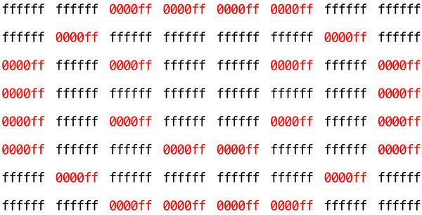
Because we’ve presented these bits from left to right, top to bottom, in 8 columns, you can actually see the red smiley if you take a step back.
To be clear, recall that a hexadecimal digit represents 4 bits. Accordingly, ffffff in hexadecimal actually signifies 111111111111111111111111 in binary.
Notice that you could represent a bitmap as a 2-dimensional array of pixels: where the image is an array of rows, each row is an array of pixels. Indeed, that’s how we’ve chosen to represent bitmap images in this problem.
Image Filtering
What does it even mean to filter an image? You can think of filtering an image as taking the pixels of some original image, and modifying each pixel in such a way that a particular effect is apparent in the resulting image.
Pixelate
The pixelate filter creates a mosaic effect by dividing the image into square blocks and replacing all pixels within each block with the average color of that block. This effect is commonly seen in images where faces or sensitive information needs to be obscured.
To implement the pixelate filter, you’ll need to:
- Divide the image into blocks of a fixed size (use a block size of 10×10 pixels)
- For each block, calculate the average red, green, and blue values of all pixels within that block
- Replace every pixel in the block with this averaged color
Important considerations:
- Images may not divide evenly by the block size. When you reach the right or bottom edge of the image, you may have partial blocks (for example, if the image width is 47 pixels and your block size is 10, the rightmost blocks will only be 7 pixels wide). Handle these partial blocks by calculating the average over only the pixels that actually exist.
- Remember to round your averages to the nearest integer when assigning them back to pixel values.
- You’ll need to calculate and store the average for each block before applying it to avoid using already-modified pixel values in your calculations.
Example: If you have a 3×3 image where all pixels have different colors, and your block size is 10 (larger than the image), the entire image becomes one block. All nine pixels would be replaced with the average color of those nine pixels, creating a solid-colored 3×3 image.
Vignette
The vignette filter creates a vintage photograph effect by gradually darkening the edges and corners of an image while keeping the center bright. This draws the viewer’s eye toward the center of the image.
To implement the vignette filter, you’ll need to:
- Calculate the center point of the image
- For each pixel, calculate its distance from the center
- Use this distance to determine how much to darken the pixel (pixels farther from center should be darker)
- Apply the darkening by multiplying each color channel by a darkening factor
The mathematical approach:
- Calculate the distance from a pixel at position
(row, col)to the center using the distance formula:distance = √((col - center_x)² + (row - center_y)²) - Normalize this distance by dividing by the maximum possible distance (the distance from the center to a corner):
max_distance = √(center_x² + center_y²) - Calculate the darkening factor using a quadratic falloff:
factor = 1.0 - (normalized_distance² × VIGNETTE_STRENGTH), whereVIGNETTE_STRENGTH = 1.2 - Ensure the factor doesn’t go below 0 (clamp negative values to 0)
- Multiply each color channel (red, green, blue) by this factor and round to the nearest integer
Important considerations:
- Pixels at the center (distance = 0.0) will have a factor close to 1.0, meaning they stay bright
- Pixels at the corners (distance = max_distance) will have a factor close to or equal to 0.0, meaning they become very dark or black
- Don’t forget to use floating-point arithmetic for your calculations, but convert back to integers when assigning to pixel values
- The
math.hlibrary providessqrt()for square root calculations
Example: In a 3×3 image, the center pixel should remain relatively unchanged, edge pixels should be moderately darkened, and corner pixels should become very dark or completely black, creating a smooth gradient from bright center to dark edges.
Edges
In artificial intelligence algorithms for image processing, it is often useful to detect edges in an image: lines in the image that create a boundary between one object and another. One way to achieve this effect is by applying the Sobel operatorto the image.
Like image blurring, edge detection also works by taking each pixel, and modifying it based on the 3x3 grid of pixels that surrounds that pixel. But instead of just taking the average of the nine pixels, the Sobel operator computes the new value of each pixel by taking a weighted sum of the values for the surrounding pixels. And since edges between objects could take place in both a vertical and a horizontal direction, you’ll actually compute two weighted sums: one for detecting edges in the x direction, and one for detecting edges in the y direction. In particular, you’ll use the following two “kernels”:
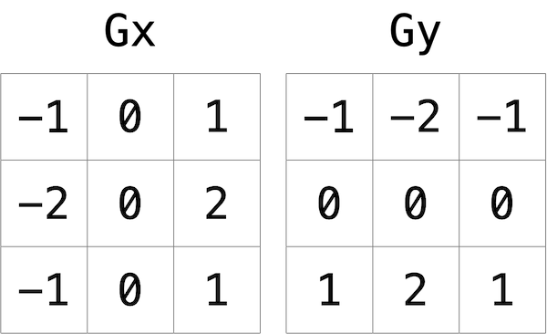
How to interpret these kernels? In short, for each of the three color values for each pixel, we’ll compute two values Gx and Gy. To compute Gx for the red channel value of a pixel, for instance, we’ll take the original red values for the nine pixels that form a 3x3 box around the pixel, multiply them each by the corresponding value in the Gx kernel, and take the sum of the resulting values.
Why these particular values for the kernel? In the Gx direction, for instance, we’re multiplying the pixels to the right of the target pixel by a positive number, and multiplying the pixels to the left of the target pixel by a negative number. When we take the sum, if the pixels on the right are a similar color to the pixels on the left, the result will be close to 0 (the numbers cancel out). But if the pixels on the right are very different from the pixels on the left, then the resulting value will be very positive or very negative, indicating a change in color that likely is the result of a boundary between objects. And a similar argument holds true for calculating edges in the y direction.
Using these kernels, we can generate a Gx and Gy value for each of the red, green, and blue channels for a pixel. But each channel can only take on one value, not two: so we need some way to combine Gx and Gy into a single value. The Sobel filter algorithm combines Gx and Gy into a final value by calculating the square root of Gx^2 + Gy^2. And since channel values can only take on integer values from 0 to 255, be sure the resulting value is rounded to the nearest integer and capped at 255!
And what about handling pixels at the edge, or in the corner of the image? There are many ways to handle pixels at the edge, but for the purposes of this problem, we’ll ask you to treat the image as if there was a 1 pixel solid black border around the edge of the image: therefore, trying to access a pixel past the edge of the image should be treated as a solid black pixel (values of 0 for each of red, green, and blue). This will effectively ignore those pixels from our calculations of Gx and Gy.
Getting Started
Here’s how to download this problem’s “distribution code” (i.e., starter code). Log into your Codespace and then, in a terminal window, execute each of the below.
- Execute
cdto ensure you’re in~/(i.e. your home directory). - Execute the following to download a (compressed) ZIP file with this assignment’s distribution:
wget https://scienceacademy.github.io/web/filter-more.zip
- Execute
unzip filter-more.zipto uncompress that file. - You’ll now see a
filter-moredirectory in your file list. - It contains the following files:
bmp.h,filter.c,helpers.h,helpers.c, andMakefile. You’ll also see a directory calledimageswith some sample bitmaps.
Understanding
Now let’s take a look at some of the files provided to you as distribution code to get an understanding for what’s inside of them.
bmp.h
Open up bmp.h (by double-clicking on it in the file browser) and have a look.
You’ll see definitions of the headers we’ve mentioned (BITMAPINFOHEADER and BITMAPFILEHEADER). In addition, that file defines BYTE, DWORD, LONG, and WORD, data types normally found in the world of Windows programming. Notice how they’re just aliases for primitives with which you are (hopefully) already familiar. It appears that BITMAPFILEHEADER and BITMAPINFOHEADER make use of these types.
Most importantly for you, this file also defines a struct called RGBTRIPLE that, quite simply, “encapsulates” three bytes: one blue, one green, and one red (the order, recall, in which we expect to find RGB triples actually on disk).
Why are these structs useful? Well, recall that a file is just a sequence of bytes (or, ultimately, bits) on disk. But those bytes are generally ordered in such a way that the first few represent something, the next few represent something else, and so on. “File formats” exist because the world has standardized what bytes mean what. Now, we could just read a file from disk into RAM as one big array of bytes. And we could just remember that the byte at array[i] represents one thing, while the byte at array[j] represents another. But why not give some of those bytes names so that we can retrieve them from memory more easily? That’s precisely what the structs in bmp.h allow us to do. Rather than think of some file as one long sequence of bytes, we can instead think of it as a sequence of structs.
filter.c
Now, open up filter.c. This file has been written already for you, but there are a couple important points worth noting here.
First, notice the definition of filters on line 11. That string tells the program what the allowable command-line arguments to the program are: b, g, r, and s. Each of them specifies a different filter that we might apply to our images: blur, grayscale, reflection, and sepia.
The next several lines open up an image file, make sure it’s indeed a BMP file, and read all of the pixel information into a 2D array called image.
Scroll down to the switch statement that begins on line 102. Notice that, depending on what filter we’ve chosen, a different function is called: if the user chooses filter b, the program calls the blur function; if g, then grayscale is called; if r, then reflect is called; and if s, then sepia is called. Notice, too, that each of these functions take as arguments the height of the image, the width of the image, and the 2D array of pixels.
These are the functions you’ll implement. As you might imagine, the goal is for each of these functions to edit the 2D array of pixels in such a way that the desired filter is applied to the image.
The remaining lines of the program take the resulting image and write them out to a new image file.
helpers.h
Next, take a look at helpers.h. This file is quite short, and just provides the function prototypes for the functions named earlier.
Take note of the fact that each function takes a 2D array called image as an argument, where image is an array of height many rows, and each row is itself another array of width many RGBTRIPLEs. So if image represents the whole picture, then image[0] represents the first row, and image[0][0] represents the pixel in the upper-left corner of the image.
helpers.c
Finally, open helpers.c. Here’s where the implementation of the functions declared in helpers.h belong. Right now, the implementations are missing! This part is up to you.
Makefile
There’s also a Makefile, which specifies what happens when you run make filter. In the past, we’ve written programs that were confined to just one file, but this project contains multiple: filter.c, ‘helpers.h, and helpers.c. Makefile` tells the compiler how to include those files.
Try compiling filter by running
$ make filter
Then you can run the program with
$ ./filter -g images/yard.bmp out.bmp
This generates a new image called out.bmp after calling the grayscale function. grayscale doesn’t do anything yet, though, so the output image just matches the original.
Specification
Implement the functions in helpers.c.
- The function
grayscaleshould take an image and turn it into a black-and-white version of the same image. - The
reflectfunction should take an image and reflect it horizontally. - The
blurfunction should take an image and turn it into a box-blurred version of the same image. - The
edgesfunction should take an image and highlight the edges between objects, using the Sobel operator.
You should not modify any of the function signatures, nor should you modify any other files other than helpers.c.
Hints
- The values of a pixel’s
rgbtRed,rgbtGreen, andrgbtBluecomponents are all integers, so be sure to round any floating-point numbers to the nearest integer when assigning them to a pixel value!
Testing
Be sure to test all of your filters on the example bitmaps!
Execute the below to evaluate the correctness of your code using check50. But be sure to compile and test it yourself as well!
check50 scienceacademy/problems/2025ap/filter/more
How to Submit
Execute the below to submit your code:
submit50 scienceacademy/problems/2025ap/filter/more